|
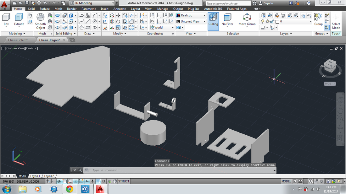
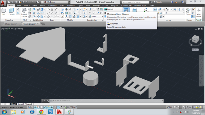
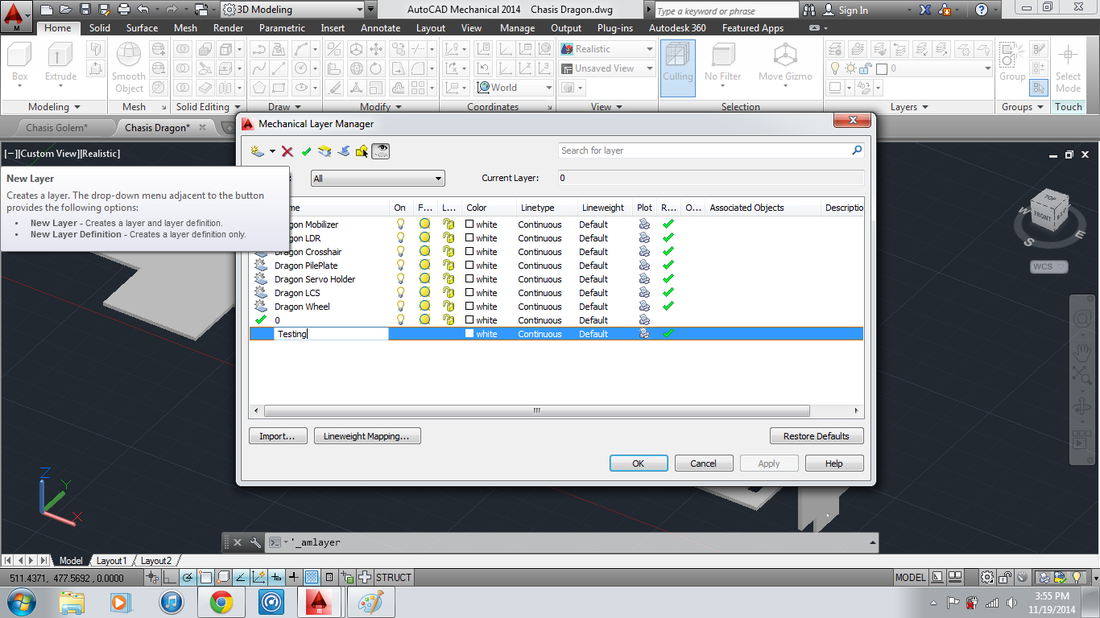
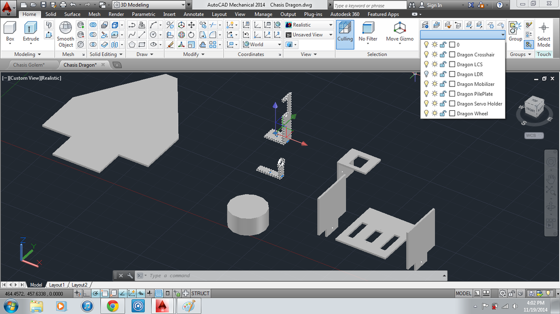
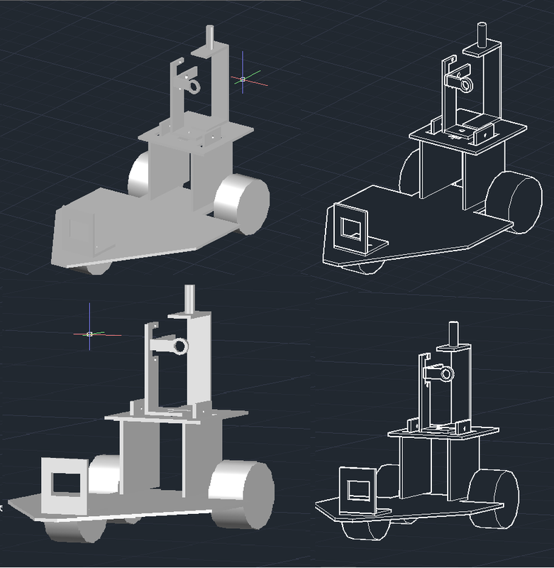
Industrial machinery is capable of realise AutoCAD drawing into reality. Each of the parts of the design will be done by 1 or multiple machines. Here below is example of AutoCAD drawing design that is a project of a SGU student Thesis, Jesse Naftali. AutoCAD which are program in designing mechanical part preferred by most Industrial Company, are just as powerful as SolidWork, one of the feature of AutoCAD is the layer which ease us in temporarily removing any object so it will not clash other object. Layer could be created by clicking the mechanical layer manager and then upon seeing the dialog box, click on New layer and enter the name of the layer. Once the Layer is created, it can be used to group object into layer simply by selecting the object and then list down the layer that you want to grouped that object with. To remove the object temporarily from the scene is to click on the light (little lamp) symbol to activate or deactivate. back to topic of machining parts, the part that are basically cylinder can be form and shaped by CNC Lathe or Lathe (making round or holes with desirable diameter) or Bandsaws (cutting round/rectangle metal object to get the width desired) machine. Meanwhile the rectangle part can be shaped and form by using Milling/ Wirecut. Complex object like the Big Plate are designed using the Wirecut or Milling. Beside Lathe, Radial Bore and Bore Fraise can also be used to create holes.
Click on the Link provided to get to know what the machine looks like and how it works or just go to our Store Front. Topic on AutoCAD Tips & Trick and what is the feature will be on the next post in greater detail. Like our Facebook page at www.facebook.com/majujayamachinery to get inform about the next post release. Here is the Preview of assembled part of a Laser-Tag Cars |
AuthorHenry Gunawan H Archives
November 2022
Categories
All
|
Maju Jaya MachineryJakartaMain Mobile: +62 81331333838
Mobile: +628883020992 / +6282231383858 Email: mjm168fu@yahoo.com / henrygh_mjm@yahoo.com Address: Hussain Sastra Negara, Nusa Indah Blok B No-76, Near Soetta Airport SurabayaPhone: +6231 7493838
Mobile: +62811333838 / +628883020992 Email: mjm168fu@yahoo.com / henrygh_mjm@yahoo.com Address: Margomulyo Permai Block F-20, Surabaya, Indonesia |
Sitemap |
Find Us at |
 RSS Feed


